The isolation resistance is measured during every restart of the inverter and also during operation. In case your inverter displays an earth fault (E34 Insulation), be aware that an isolation error is a severe risk which can result in fire or electric shock. To mitigate this risk, it is necessary to measure the isolation resistance.
Measurement of isolation Resistance
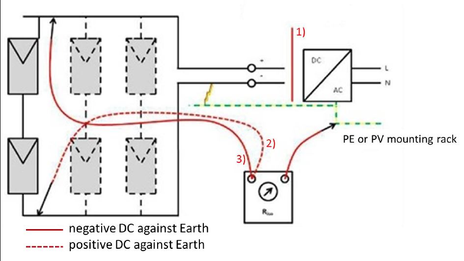
- Disconnect DC at isolator switch/ remove any SPD
- Measure resistance between positive DC & Earth
- Measure resistance between negative DC & Earth
The applied test voltage for the measurement depends on the open circuit voltage of your system. The value for the system voltage is calculated by multiplying the open circuit voltage by a factor of 1.25. In table 1 you can find the minimum isolation resistance depending on the size of your system.
The actual resistance values can be higher or lower, depending upon factors as the temperature or moisture content of the insulation (resistance decreases in temperature or moisture). With a little record-keeping and common sense, however, you can get a good picture of the insulation condition from values that are only relative.
There are several commercial PV testing devices available in the market which will test the PV system and provide a report. You may want to consider using such kind of device.